QS Energy Provides AOT Testing Update
Update on AOT component testing
CARSON CITY, NV / ACCESSWIRE / October 7, 2021 / QS Energy, Inc. (the "Company" or "QS Energy") (OTCQB:QSEP), a developer of integrated technology solutions for the energy industry, today provided an update to our press release of September 27, 2021.
Cecil Bond Kyte, Chief Executive Officer and Chairman of the Board, commented, "From May 2021 to present we have conducted many tests designed to isolate components and variables on the grid pack and we have found locations where arcing occurred unexpectedly. In this investor update we will share some of our key findings. Furthermore, we plan to implement and test some of these design changes in the coming weeks."
Dr. Christopher Gallagher explained, "The inability to achieve treatment field strength has been a recurring theme through the demonstration project, where we were under contract to provide services to our partner, which ended in June of 2020. While at the demonstration site, all components were concealed in the AOT and the inconsistency of results made it very difficult to positively diagnose problems and implement solutions. Now, isolating components and parameters has allowed us to identify and replicate arcing events while observing where they occurred. Knowing these points will give us an opportunity to improve the design of the current AOT."
Key findings that prevented the AOT from operating during the Demonstration Project
A few major issues have prevented the AOT from achieving the voltage necessary to apply the AOT technology at the previous demonstration site. A conceptual drawing of the grid pack is shown in Diagram 1 with the locations of the problems identified with arrows.
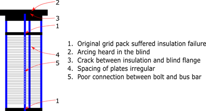
Diagram 1: Conceptual Drawing of Current Stack
The original grid pack installed at the demonstration site was recently found to have two locations where the electrical insulation had been damaged, and arcing limited the amount of voltage that could be applied. By isolating the components, we were able to recreate the failure in the original grid pack. The electrical insulation appears to have suffered many arcs and has melted. It is likely the damage started as a point failure and grew with more energy discharge. While we were not able to create a short circuit, it is possible and perhaps even likely the gaps became filled with carbon due to the electrical discharge, which led to a short circuit during the demonstration.
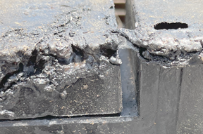
Figure 1: Photo of damaged insulation.
As reported on September 13, 2019 in the Demonstration Project Status Update, the original AOT grid pack was replaced with the current grid pack to improve the intended reliability of the AOT by eliminating locations of potential arcing and short circuits. The implemented changes seemed to prevent damage like what is shown in Figure 1. We have been able to achieve higher voltages without similar damage. We believe this points to the new materials of construction being better for our application.
As a result of our recent testing of the AOT, we discovered the blind flange required additional evaluation. Throughout testing, it was determined the blind presented some issues as well. Arcing can be heard from inside the blind. Additionally, a crack has formed where the insulation was cast on the blind flange-see Figure 2. The crack may only be a surface crack, or it may be a separation which could allow fluid to penetrate.
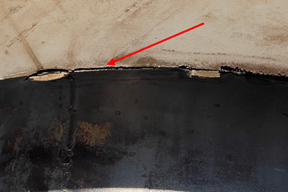
Figure 2: Insulation at blind flange.
We also observed that the electrical insulation separated from the pressure vessel-see Figure 3. This observation has not yet correlated with any operational limitations and may not need to be addressed.
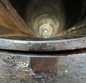
Figure 3: Pressure vessel insulation.
We found that the current internals had significant spacing variation as indicated in Diagram 1 item 4. During the demonstration project the issue had been noted and insulated spacers were designed and made to improve plate spacing and to provide additional electrical isolation to the shell. The spacers worked to a degree, but we noted variation in plate spacing was still present. Given the limited voltage we had been able to achieve, it was not deemed a major issue at the time. During recent testing, we found that when the plates were isolated, arcing occurred at the closest point between them as expected. By investigating the grid pack where arcs formed, we found that there were a few locations where the gap decreased to almost half of the designed gap toward the centerline of the grid pack.
One of the major issues was arcing between assembly bolts and the negative bus bar. This issue was caused by the mechanical failure of spacers connecting the plates to the bus bar. The collapsed spacer created a very small gap, where there should have been strong metal to metal contact to connect, between the bolt and the bus bar. The gap allowed arcs to occur. Replacement spacers eliminated the issue.
We have gathered facts about the issues that prevented us to increase voltage beyond a nominal value. The plan has been implemented with the improvements for the internals to eliminate the identified problems.
The collective analysis and ultimate redesign should carry us through to a new demonstration. It is our expectation when we re-demonstrate our technology that we will not endure the failures of last year. As the design changes are implemented, we expect to test with oil from the demonstration site to validate the final design.
In closing, we are confident that a retest in the presence of a development partner will yield to the expectations prior to June 2020. Furthermore, despite any supply chain issues, we expect to be testing in the next few weeks. Pending a positive outcome, we should be able to move forward towards a demonstration test in the presence of a development partner.
For further information about QS Energy, Inc., visit www.QSEnergy.com, read our SEC filings at https://ir.stockpr.com/qsenergy/all-sec-filings and subscribe to Email Alerts at https://ir.stockpr.com/qsenergy/email-alerts to receive Company news and shareholder updates.
Safe Harbor Statement
Some of the statements in this release may constitute forward-looking statements under federal securities laws. Please visit the following link for our complete cautionary forward-looking statement: https://www.qsenergy.com/site-info/disclaimer
About Applied Oil Technology
QS Energy's patented Applied Oil Technology (AOT) is a solid-state turn-key system which uses a high volt / low amp electric field to reduce crude oil viscosity. AOT installs inline on crude oil pipelines, operates unattended without interrupting pipeline flow, with full remote monitoring and control. More information is available online at www.qsenergy.com.
About QS Energy
QS Energy, Inc. (OTCQB:QSEP), develops and markets crude oil flow assurance technologies designed to deliver measurable performance improvements to pipeline operations in the midstream and upstream crude oil markets. More information is available at www.qsenergy.com.
Company Contact:
QS Energy, Inc.
Tel: +1 844-645-7737
E-mail: investor@qsenergy.com
Sales: sales@qsenergy.com
SOURCE: QS Energy, Inc.
View source version on accesswire.com:
https://www.accesswire.com/667096/QS-Energy-Provides-AOT-Testing-Update
Released October 7, 2021